Search Keywords: “QuickPipe“, “Pipe Design“, “Pressure Loss“ in iPhone App Store

To show you how QuickPipe can facilitate the design and reduce the time to market, let us take the following case as an example for demonstration.
This is a complete cooling system which consists of an outdoor dry cooler, a control unit with pump, manifold and cold plates to transfer the heat from a customer facility to outdoor.
The customer facility is a device that has 6 IGBT boards inside and each board has a heat dissipation of 3.6kW.
They are placed one on another and a cold plate with running water will be attached to the IGBT to absorb the heat and cool such IGBTs within the temperature limit.
There is a control unit with pump inside to generate the required water flow rate for cooling. Of course at the design stage the capacity of such pump is to be determined based on the overall pressure loss of the whole pipework. The water being heated by the IGBTs will next go inside the coils of an outdoor cooling tower. The cooling tower is designed so that the water leaving it will be 30℃ at the maximum.
The parts of such system are arranged in position so that the pipe length from the cooling tower to the control unit is around 11m, from the control unit to the manifolds is 3m and from the manifolds to the cold plates is 1m.
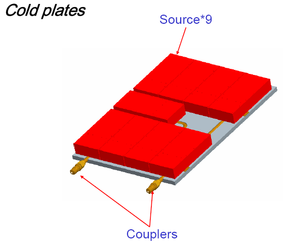
We will start from the IGBT boards to determine the necessary flow rate of the overall system. As shown in the figure above, there are 9 IGBTs on each board. It is a common practice that the engineer will use any of the CFD software to help determine the required flow rate into such cold plate. The design target is usually to keep the temperature of any IGBT under the allowable limit. By using such CFD software, we determine that the flow rate into each of the cold plate should be at least 11.355LPM.

With such number in mind, we can obtain the leaving water temperature from the cold plates by QuickPipe. Since the flow rate is known as 11.355LPM, we will use Page 4 of QuickPipe for “Heatload <-> ΔT” calculations. Before jumping into Page 4, we would suggest that you check the page of “Unit Setting” first to make sure that the temperature is in ℃, the volume flow rate in LPM and the heatload in kW. Since the entering water temperature to the cold plates is 30℃, we first change the index of fluid to be 6. We then input the initial temperature as 30degC and the volume flow rate as 11.355LPM. Since we already know the heat absorbed by the water is 3.6kW, we can tap the segmented control to the top right of the page as “Heatload to ΔT” then input 3.6kW as Rate of Heat Absorbed. Immediately after you complete the input of 3.6kW, you will see 34.57019degC as the resulting final temperature.

Since both the flow rate and temperature are known to us, the next step would be the determination of correct pipe size for each segment of this system. On the cold plate itself, copper tube of Type K is often used as the cooling tube embedded. Therefore we move on to Page 6, the “Pressure Loss of Water” to determine the correct size of the pipes/tubes. As we move the slider bar of “Index of metal tube” from 1, we will see the “Rec. Max Flow Rate” of index #1 is 6.8963LPM, that of index #2 is 11.98LPM and that of index #6 is 73.394LPM.


As we already know the flow rate of each cold plate is 11.355LPM, index #2 or 3/8” Copper tube of Type K is what we want. Similarly, the overall flow rate of six such cold plates is 68.13LPM and index #6 or 1” Copper tube of Type K is also what we need. Should the customer prefer hoses for the connection in between the control unit and the manifolds, we can change from “Metal Tube” to “Hose” in Page #5. In such case, we will see the “Rec. Max Flow Rate” of index #2 Hose is 10.812LPM, that of index #3 is 18.533LPM.


Because of the fact that the inside diameter of hoses is smaller than pipes/tubes of the same nominal size, the recommended maximum flow rate will be smaller. Here there is no definite answer to choose #2 (3/8”) or #3 (1/2”) hoses since the “Rec. Max Flow Rate” is based on the empirical rule that the fluid velocity inside pipes/tubes/hoses should not exceed 8ft/sec. Since we require a flow rate of 11.355LPM which is just a little larger than 10.812LPM, #2 (3/8”) hose should be a better answer considering the larger bending radius of larger hoses.
So far we’ve determined the temperatures and the pipe/hose sizes of each segment of this system. We can generate a table similar to the one below.
Segment #
|
Description
|
Tubes/Pipes/Hoses
|
Length (m)
|
Volume Flow Rate (LPM)
|
Predicted Pressure Loss by Quick Pipe (mH2O)
|
1
|
Control unit to manifold
|
1” hose (Couplings on both ends)
|
3
|
68.13
|
0.702104
|
2
|
Manifold to I/O of cold plates
|
3/8” hose (Couplings on both ends)
|
1
|
11.355
|
0.855244
|
3
|
Inside cold plate
|
3/8” Copper Tube of Type K (with 6 internal turns)
|
1.4
|
11.355
|
1.468238
|
4
|
Cold plates to manifold
|
3/8” hose (Couplings on both ends)
|
1
|
11.355
|
0.855244
|
5
|
Manifold to dry cooler
|
1” hose (Couplings on both ends)
|
14
|
68.13
|
3.276486
|
6
|
Dry cooler to control unit
|
1” hose (Couplings on both ends)
|
11
|
68.13
|
2.574382
|
Overall
Pressure Loss excluding the manifold and dry cooler (mH2O)
|
9.731698
|
||||
Screenshot of #1:


Screenshot of #5:

Screenshot of #6:

沒有留言:
張貼留言